
Page 424 - Mechanics of Asphalt Microstructure and Micromechanics
P. 424
T
416 Ch a p t e r w e l v e
0.09
0.08
0.07
Tensile Deformation (mm) 0.05 Sapmple 1
0.06
0.04
0.03
Sample 3
Sample 4
0.02 Sample 2
Sample 5
0.01 Sample 6
Line of Equity
0
0 0.01 0.02 0.03 0.04 0.05 0.06 0.07 0.08 0.09
Compressive Deformation (mm)
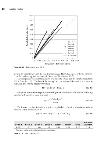
FIGURE 12.16 Deformations at 25°C.
around 1.6 times larger than the tensile modulus, E t . This value agrees with the observa-
tions derived from previous research (Secor and Monismith, 1965).
The compressive deformation curve was used to obtain the deformation function,
Δ(t) in Equation 12-21. The best fit for the typical compressive deformation process was
regressed as a second-order polynomial:
Δ()=× −52 4 −4 t (12-22)
t + × 10
210
t
A Laplace transform was performed on Equation 12-20 and 12-21 and the following
transformed functions were obtained:
AP s ()+ A q s ()
Es ()= 1 2 (12-23)
Δ
s ()
s
The inverse Laplace transform was then applied to obtain the relaxation modulus
function in the time domain as:
×
×
11
Et ()=1 .524 10 10 e −0 .1 t − . 1 574 10 δ t () (12-24)
Standard
Beam 1 Beam 2 Beam 3 Beam 4 Beam 5 Beam 6 Mean Deviation
1.97* 1.27 1.48 1.16 1.14 1.34 1.28 0.14
* This is an outlier and not included in the calculation
Table 12.4 The r ratio at 25°C.