
Page 137 - Mechanics of Microelectromechanical Systems
P. 137
124 Chapter 2
and, in addition: By using these particular values the stiffness
given in Eq. (2.184) has been obtained, and this validates the more generic
model developed here.
Example 2.19
Determine the bending stiffness connected to the midpoint of a
microbridge which is formed of two identical segments of length l and
constant cross-section of moment of inertia that are placed at the ends and
are adjacent to a middle segment of length l and constant cross-section with
Solution:
The compliances of the two different compliant segments are:
where i = 1, 2. By using the particular parameters of this problem, it is found
that the linear stiffness is:
Example 2.20
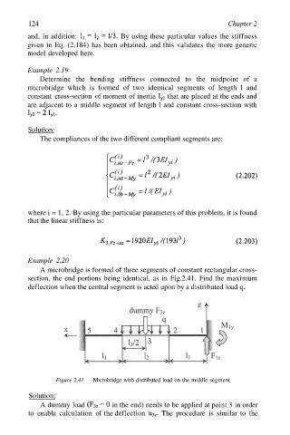
A microbridge is formed of three segments of constant rectangular cross-
section, the end portions being identical, as in Fig.2.41. Find the maximum
deflection when the central segment is acted upon by a distributed load q.
Figure 2.41 Microbridge with distributed load on the middle segment
Solution;
A dummy load in the end) needs to be applied at point 3 in order
to enable calculation of the deflection The procedure is similar to the