
Page 134 - Mechanics of Microelectromechanical Systems
P. 134
2. Microcantilevers, microhinges, microbridges 121
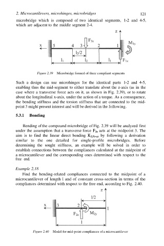
microbridge which is composed of two identical segments, 1-2 and 4-5,
which are adjacent to the middle segment 2-4.
Figure 2.39 Microbridge formed of three compliant segments
Such a design can use microhinges for the identical parts 1-2 and 4-5,
enabling thus the mid-segment to either translate about the z-axis (as in the
case where a transverse force acts on it, as shown in Fig. 2.39), or to rotate
about the longitudinal x-axis, under the action of a torque. As a consequence,
the bending stiffness and the torsion stiffness that are connected to the mid-
point 3 might present interest and will be derived in the following.
5.3.1 Bending
Bending of the compound microbridge of Fig. 2.39 will be analyzed first
under the assumption that a transverse force acts at the midpoint 3. The
aim is to find the linear direct bending by following a derivation
similar to the one detailed for single-profile microbridges. Before
determining the sought stiffness, an example will be solved in order to
establish connections between the compliances calculated at the midpoint of
a microcantilever and the corresponding ones determined with respect to the
free end.
Example 2.18
Find the bending-related compliances connected to the midpoint of a
microcantilever of length l and of constant cross-section in terms of the
compliances determined with respect to the free end, according to Fig. 2.40.
Figure 2.40 Model for mid-point compliances of a microcantilever