
Page 129 - Mechanics of Microelectromechanical Systems
P. 129
116 Chapter 2
For all these designs, stiffnesses or compliances have been derived at the
free end with respect to the opposite fixed one. It is considered that the
microbridge has a variable cross-section and is symmetric about both the
longitudinal and transverse axes in its front section, as indicated in Fig. 2.36.
These features will enable expressing the sought stiffnesses of the whole
microstructure in terms of the compliances that have already been defined for
half the structure.
5.2.1 Bending
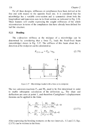
The z-direction stiffness at the midspan of a microbridge can be
determined by considering that a force loads the fixed-fixed beam
(microbridge) shown in Fig. 2.37. The stiffness of this beam about the z-
direction at the midpoint can be calculated as:
Figure 2.37 Microbridge loaded with a force at its midpoint
The two unknown reactions ... and need to be first determined in order
to enable subsequent calculation of the deflection The slope and
deflection are zero at point 1, and therefore Castigliano’s displacement
theorem can be applied in the form:
After expressing the bending moments on the two intervals, 1-2 and 2-3, Eqs.
(2.171) can be written in the form: