
Page 128 - Mechanics of Microelectromechanical Systems
P. 128
2. Microcantilevers, microhinges, microbridges 115
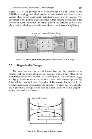
Figure 2.35 is the photograph of a microbridge built by means of the
MUMPs technology and which consists of two notched areas that border a
central plate where electrostatic actuation/sensing can be applied. The
advantage of this particular configuration is that bending is localized at the
two notch regions such that the central portion can perform an out-of-the-
plane motion, which more closely resembles the translation of a rigid body.
Figure 2.35 Prototype microbridge with two circular corner-filleted hinges
5.2 Single-Profile Designs
The main motions that are of interest here are the out-of-the-plane
bending and the torsion about an axis passing longitudinally through the
microbridge and its two anchors. As a consequence, two stiffnesses,
and both evaluated at the symmetry center of the microbridge (see Fig.
2.36) will be calculated next. Examples of this generic design include the
constant rectangular cross-section, the circularly-filleted, the right-circular
and right-elliptic configurations that have been analyzed in this chapter’s
section dedicated to microhinges.
Figure 2.36 Microbridge of double symmetry