
Page 124 - Mechanics of Microelectromechanical Systems
P. 124
2. Microcantilevers, microhinges, microbridges 111
The stiffness of the first design can be found by taking in Eq.
(2.160) and the stiffness of the second design also results from Eq. (2.160)
when taking The ratio of the two stiffnesses is plotted in Fig. 2.30. It
can be seen that the stiffness of the microcantilever with can be up
to 15 % higher than the stiffness of the design with
Example 2.15
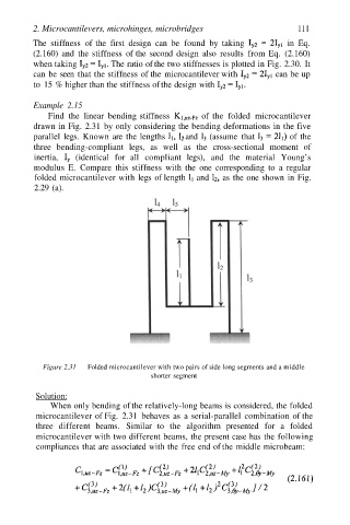
Find the linear bending stiffness of the folded microcantilever
drawn in Fig. 2.31 by only considering the bending deformations in the five
parallel legs. Known are the lengths and (assume that of the
three bending-compliant legs, as well as the cross-sectional moment of
inertia, (identical for all compliant legs), and the material Young’s
modulus E. Compare this stiffness with the one corresponding to a regular
folded microcantilever with legs of length and as the one shown in Fig.
2.29 (a).
Figure 2.31 Folded microcantilever with two pairs of side long segments and a middle
shorter segment
Solution:
When only bending of the relatively-long beams is considered, the folded
microcantilever of Fig. 2.31 behaves as a serial-parallel combination of the
three different beams. Similar to the algorithm presented for a folded
microcantilever with two different beams, the present case has the following
compliances that are associated with the free end of the middle microbeam: