
Page 125 - Mechanics of Microelectromechanical Systems
P. 125
112 Chapter 2
where the individual compliances of the three microbeams are indicated by
the superscripts 1,2 and 3.
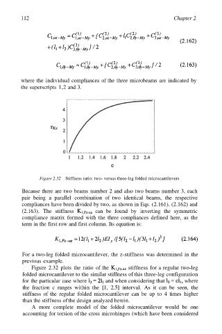
Figure 2.32 Stiffness ratio: two- versus three-leg folded microcantilevers
Because there are two beams number 2 and also two beams number 3, each
pair being a parallel combination of two identical beams, the respective
compliances have been divided by two, as shown in Eqs. (2.161), (2.162) and
(2.163). The stiffness can be found by inverting the symmetric
compliance matrix formed with the three compliances defined here, as the
term in the first row and first column. Its equation is:
For a two-leg folded microcantilever, the z-stiffness was determined in the
previous example.
Figure 2.32 plots the ratio of the stiffness for a regular two-leg
folded microcantilever to the similar stiffness of this three-leg configuration
for the particular case where and when considering that where
the fraction c ranges within the [1, 2.5] interval. As it can be seen, the
stiffness of the regular folded microcantilever can be up to 4 times higher
than the stiffness of the design analyzed herein.
A more complete model of the folded microcantilever would be one
accounting for torsion of the cross microhinges (which have been considered