
Page 121 - Mechanics of Microelectromechanical Systems
P. 121
108 Chapter 2
By using the data of this example, the numerical value of the attached mass is
4.2 Folded Microcantilevers
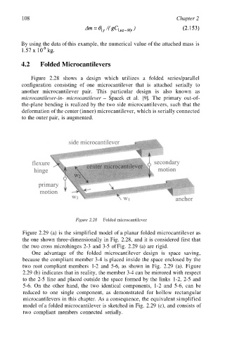
Figure 2.28 shows a design which utilizes a folded series/parallel
configuration consisting of one microcantilever that is attached serially to
another microcantilever pair. This particular design is also known as
microcantilever-in- microcantilever – Spacek et al. [9]. The primary out-of-
the-plane bending is realized by the two side microcantilevers, such that the
deformation of the center (inner) microcantilever, which is serially connected
to the outer pair, is augmented.
Figure 2.28 Folded microcantilever
Figure 2.29 (a) is the simplified model of a planar folded microcantilever as
the one shown three-dimensionally in Fig. 2.28, and it is considered first that
the two cross microhinges 2-3 and 3-5 of Fig. 2.29 (a) are rigid.
One advantage of the folded microcantilever design is space saving,
because the compliant member 3-4 is placed inside the space enclosed by the
two root compliant members 1-2 and 5-6, as shown in Fig. 2.29 (a). Figure
2.29 (b) indicates that in reality, the member 3-4 can be mirrored with respect
to the 2-5 line and placed outside the space formed by the links 1-2, 2-5 and
5-6. On the other hand, the two identical components, 1-2 and 5-6, can be
reduced to one single component, as demonstrated for hollow rectangular
microcantilevers in this chapter. As a consequence, the equivalent simplified
model of a folded microcantilever is sketched in Fig. 2.29 (c), and consists of
two compliant members connected serially.