
Page 117 - Mechanics of Microelectromechanical Systems
P. 117
104 Chapter 2
by changing the geometry of the member, which can be done for instance by
cutting notches in the original rectangular profile. The design of a
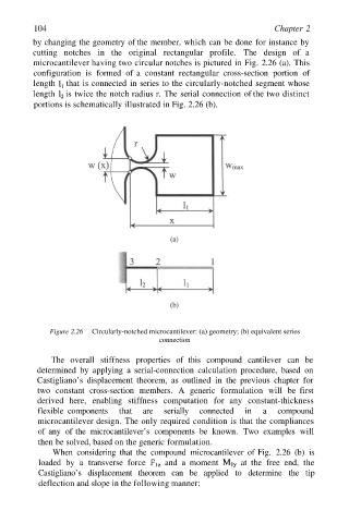
microcantilever having two circular notches is pictured in Fig. 2.26 (a). This
configuration is formed of a constant rectangular cross-section portion of
length that is connected in series to the circularly-notched segment whose
length is twice the notch radius r. The serial connection of the two distinct
portions is schematically illustrated in Fig. 2.26 (b).
Figure 2.26 Circularly-notched microcantilever: (a) geometry; (b) equivalent series
connection
The overall stiffness properties of this compound cantilever can be
determined by applying a serial-connection calculation procedure, based on
Castigliano’s displacement theorem, as outlined in the previous chapter for
two constant cross-section members. A generic formulation will be first
derived here, enabling stiffness computation for any constant-thickness
flexible components that are serially connected in a compound
microcantilever design. The only required condition is that the compliances
of any of the microcantilever’s components be known. Two examples will
then be solved, based on the generic formulation.
When considering that the compound microcantilever of Fig. 2.26 (b) is
loaded by a transverse force and a moment at the free end, the
Castigliano’s displacement theorem can be applied to determine the tip
deflection and slope in the following manner: