
Page 113 - Mechanics of Microelectromechanical Systems
P. 113
100 Chapter 2
3.2 Designs
The stiffnesses and/or compliances of the above-mentioned microhinge
configurations will be calculated for one end of the microhinge (for instance,
the right end point from where the abscissa x is measured in Figs. 2.24 (a)
and 2.25 (a)) – this end point is free and is formally denoted by 1 – with
respect to the other end which is considered fixed. Of special interest will be
the stiffnesses describing the bending about the sensitive y-axis, namely:
as well as the axial stiffness and the torsional
stiffness
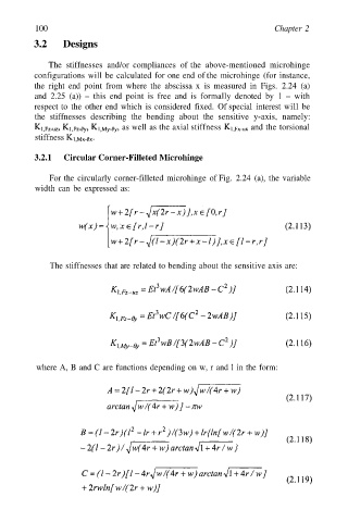
3.2.1 Circular Corner-Filleted Microhinge
For the circularly corner-filleted microhinge of Fig. 2.24 (a), the variable
width can be expressed as:
The stiffnesses that are related to bending about the sensitive axis are:
where A, B and C are functions depending on w, r and l in the form: