
Page 111 - Mechanics of Microelectromechanical Systems
P. 111
98 Chapter 2
Figure 22 (b) is the sketch of a micromirror whereby the rotational motion
about the x-axis is enabled by the torsion of the aligned hinges.
Constructively, the hinges of these two examples can be identical, only their
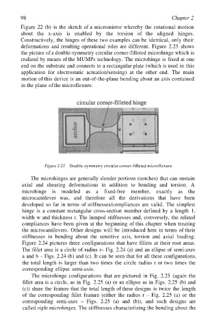
deformations and resulting operational roles are different. Figure 2.23 shows
the picture of a double-symmetry circular corner-filleted microhinge which is
realized by means of the MUMPs technology. The microhinge is fixed at one
end on the substrate and connects to a rectangular plate (which is used in this
application for electrostatic actuation/sensing) at the other end. The main
motion of this device is an out-of-the-plane bending about an axis contained
in the plane of the microflexure.
Figure 2.23 Double-symmetry circular corner-filleted microflexure
The microhinges are generally slender portions (notches) that can sustain
axial and shearing deformations in addition to bending and torsion. A
microhinge is modeled as a fixed-free member, exactly as the
microcantilever was, and therefore all the derivations that have been
developed so far in terms of stiffnesses/compliances are valid. The simplest
hinge is a constant rectangular cross-section member defined by a length 1,
width w and thickness t. The lumped stiffnesses and, conversely, the related
compliances have been given at the beginning of this chapter when treating
the microcantilevers. Other designs will be introduced here in terms of their
stiffnesses in bending about the sensitive axis, torsion and axial loading.
Figure 2.24 pictures three configurations that have fillets at their root areas.
The fillet area is a circle of radius r– Fig. 2.24 (a) and an ellipse of semi-axes
a and b – Figs. 2.24 (b) and (c). It can be seen that for all these configurations,
the total length is larger than two times the circle radius r or two times the
corresponding ellipse semi-axis.
The microhinge configurations that are pictured in Fig. 2.25 (again the
fillet area is a circle, as in Fig. 2.25 (a) or an ellipse as in Figs. 2.25 (b) and
(c)) share the feature that the total length of these designs is twice the length
of the corresponding fillet feature (either the radius r – Fig. 2.25 (a) or the
corresponding semi-axes – Figs. 2.25 (a) and (b)), and such designs are
called right microhinges. The stiffnesses characterizing the bending about the