
Page 110 - Mechanics of Microelectromechanical Systems
P. 110
2. Microcantilevers, microhinges, microbridges 97
The force corresponding to the hollow triangular microcantilever is
calculated by using Eqs. (2.99) through (2.102). These compliances have
been divided by 2 in order to account for the two members that compose the
triangular design. The force depends on the tip semi-angle for the hollow
design. Figure 2.21 plots the tip force in terms of the semi-angle.
Figure 2.21 Tip force as function of the triangular microcantilever semi-angle
a
3. MICROHINGES
3.1 Introduction
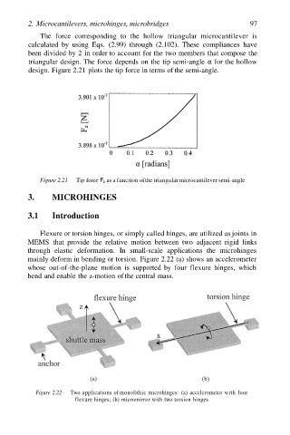
Flexure or torsion hinges, or simply called hinges, are utilized as joints in
MEMS that provide the relative motion between two adjacent rigid links
through elastic deformation. In small-scale applications the microhinges
mainly deform in bending or torsion. Figure 2.22 (a) shows an accelerometer
whose out-of-the-plane motion is supported by four flexure hinges, which
bend and enable the z-motion of the central mass.
Figure 2.22 Two applications of monolithic microhinges: (a) accelerometer with four
flexure hinges; (b) micromirror with two torsion hinges