
Page 105 - Mechanics of Microelectromechanical Systems
P. 105
92 Chapter 2
As shown previously, the tip slopes and as well as the tip
deflection might be available experimentally, which can aid in
determining the forces on the microcantilevers via compliances/stiffnesses.
2.3.1 Rectangular Design
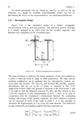
Figure 2.18 is the simplified model of a hollow rectangular
microcantilever with its defining geometry. The transverse portion of length
is usually designed to be stiffer than the two parallel segments, and
therefore this component can be considered rigid.
Figure 2.18 Hollow rectangular microcantilever
The point of interest in defining the elastic properties of this microcantilever
is point 3, where the loads do apply in AFM applications. The loads and the
resulting compliances can be separated into two subcategories, namely out-
of-the-plane and in-plane. The force and moments and generate
deformations that are out of the xy plane, as sketched in Fig. 2.18.
Application of these loads will generate 6 reactions at the fixed points 1 and
5. In order to find the unknown reactions and (shown in Fig.
2.18), the equations of zero displacements at point 1 have to be used in
conjunction with the Castigliano’s displacement theorem. By considering
bending and torsion of the parallel segments, the three unknown reactions
can be expressed in terms of the loads at point 3. It is thus possible to
determine the displacements at 3 by using the same theorem. The deflection
and rotation are bending-coupled and their equations are: