
Page 104 - Mechanics of Microelectromechanical Systems
P. 104
2. Microcantilevers, microhinges, microbridges 91
Figure 2.16 is the plot of the ratio formulated in Eq. (2.90) in terms of the
friction coefficient and the height h of the microcantilever’s tip. It can be
seen that the circularly-filleted microcantilever can rotate up to 65 % more at
its tip than the elliptical design, and that the ratio between the tip slopes of
the two designs increases quasi-linearly when both and h are increasing.
2.3 Hollow Microcantilevers
Several hollow microcantilever configurations are now analyzed, and the
trapezoid design sketched in Fig. 2.17 is one example. These
microcantilevers can be used in AFM applications where the bending
stiffness about the sensitivity axis needs to be relatively low, because this
motion is the most important one.
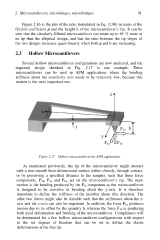
Figure 2.17 Hollow microcantilever for AFM applications
As mentioned previously, the tip of the microcantilever might interact
with a non-smooth three-dimensional surface (either directly, through contact,
or by preserving a specified distance to the sample), such that three force
components, and act on the microcantilever’s tip. The main
motion is the bending produced by the component as the microcantilever
is designed to be sensitive in bending about the y-axis. It is therefore
important to define the stiffness of the member about this direction. The
other two forces might also be sizeable such that the stiffnesses about the z-
axis and the x-axis can also be important. In addition, the force produces
torsion due to its offset by the quantity h, whereas the force is producing
both axial deformation and bending of the microcantilever. Compliances will
be determined for a few hollow microcantilever configurations with respect
to the six degrees of freedom that can be set to define the elastic
deformations at the free tip.