
Page 99 - Mechanics of Microelectromechanical Systems
P. 99
86 Chapter 2
By inverting Eq. (2.69) it is found that the related compliance matrix is:
and therefore and such that,
according to Eqs. (2.68), and
By applying a similar procedure for the bending about the z-axis, which
is produced by the force the corresponding tip displacements are:
and It can be seen that although the force is 10 times
larger than the force the displacements produced by are
approximately one order of magnitude smaller than those generated by
2.2.4 Filleted Microcantilevers
Microcantilevers that are filleted at their root by means of two circular
portions are customary designs, particularly in mass detection applications.
The circularly-filleted area is a way of reducing the stress concentrations, but
sometimes is a technological by-product, as sharp corners at a
microcantilever’s root are difficult to obtain through certain microfabrication
procedures. However, when the fillet radius is small compared to the length
and width, the fillet area is usually neglected in analytical calculations.
On occasion, the fillet radius can be relatively large, as a means of
increasing the root area, and therefore increasing the torsional stiffness for
instance. In such situations, neglecting the contribution of the fillet zone to
the various stiffnesses defining the microcantilever would amount to
unacceptable error levels. Closed form compliance equations will be
provided here (as also given in Lobontiu and Garcia [8], where a more
generic model has been proposed) for two filleted designs, namely: one with
circular areas, and the other with elliptical areas.
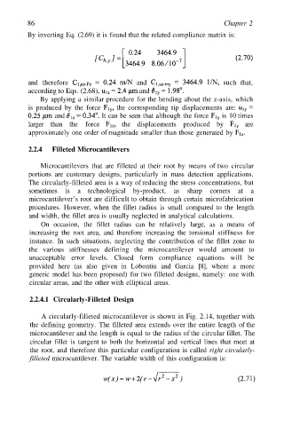
2.2.4.1 Circularly-Filleted Design
A circularly-filleted microcantilever is shown in Fig. 2.14, together with
the defining geometry. The filleted area extends over the entire length of the
microcantilever and the length is equal to the radius of the circular fillet. The
circular fillet is tangent to both the horizontal and vertical lines that meet at
the root, and therefore this particular configuration is called right circularly-
filleted microcantilever. The variable width of this configuration is: