
Page 98 - Mechanics of Microelectromechanical Systems
P. 98
2. Microcantilevers, microhinges, microbridges 85
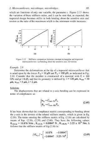
which are functions of only one variable, the parameter c. Figure 2.13 shows
the variation of these stiffness ratios, and it can be seen that, as expected, the
trapezoid design becomes stiffer in both bending about the sensitive axis and
torsion as the ratio of the maximum width to the minimum width increases.
Figure 2.13 Stiffness comparison between constant rectangular and trapezoid
microcantilevers: (a) bending about the sensitive axis; (b) torsion
Example 2.8
Determine the deformations at the tip of a trapezoid microcantilever that
is acted upon by the forces and as indicated in Fig.
2.10. Consider that the member is constructed of a material with E = 160
GPa and and that its geometry is defined by:
Solution:
The displacements that are related to y-axis bending can be expressed in
terms of compliances as:
It has been shown that the compliance matrix corresponding to bending about
the y-axis is the inverse of the related stiffness matrix, which is given in Eq.
(2.16). The terms entering the stiffness matrix of Eq. (2.16) are calculated by
means of Eqs. (2.58), (2.59) and (2.60). They have the following values:
It
follows that the stiffness matrix of Eq.(2.16) is: