
Page 112 - Mechanics of Microelectromechanical Systems
P. 112
2. Microcantilevers, microhinges, microbridges 99
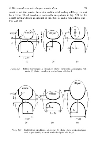
sensitive axis (the y-axis), the torsion and the axial loading will be given next
for a corner-filleted microhinge, such as the one pictured in Fig. 2.24 (a), for
a right circular design as sketched in Fig. 2.25 (a) and a right elliptic one –
Fig. 2.25 (b).
Figure 2.24 Filleted microhinges: (a) circular; (b) elliptic – large semi-axis is aligned with
length; (c) elliptic – small semi-axis is aligned with length
Figure 2.25 Right filleted microhinges: (a) circular; (b) elliptic – large semi-axis aligned
with length; (c) elliptic – small semi-axis aligned with length