
Page 166 - Mechanics of Microelectromechanical Systems
P. 166
3. Microsuspensions 153
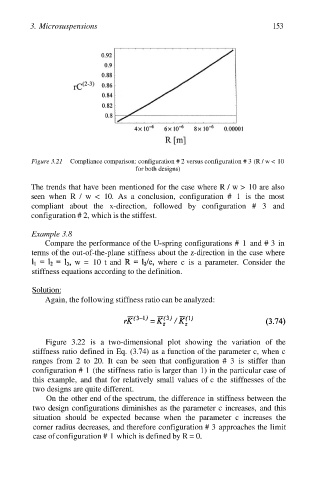
Figure 3.21 Compliance comparison: configuration # 2 versus configuration # 3 (R / w < 10
for both designs)
The trends that have been mentioned for the case where R / w > 10 are also
seen when R / w < 10. As a conclusion, configuration # 1 is the most
compliant about the x-direction, followed by configuration # 3 and
configuration # 2, which is the stiffest.
Example 3.8
Compare the performance of the U-spring configurations # 1 and # 3 in
terms of the out-of-the-plane stiffness about the z-direction in the case where
w = 10 t and where c is a parameter. Consider the
stiffness equations according to the definition.
Solution:
Again, the following stiffness ratio can be analyzed:
Figure 3.22 is a two-dimensional plot showing the variation of the
stiffness ratio defined in Eq. (3.74) as a function of the parameter c, when c
ranges from 2 to 20. It can be seen that configuration # 3 is stiffer than
configuration # 1 (the stiffness ratio is larger than 1) in the particular case of
this example, and that for relatively small values of c the stiffnesses of the
two designs are quite different.
On the other end of the spectrum, the difference in stiffness between the
two design configurations diminishes as the parameter c increases, and this
situation should be expected because when the parameter c increases the
corner radius decreases, and therefore configuration # 3 approaches the limit
case of configuration # 1 which is defined by R = 0.