
Page 167 - Mechanics of Microelectromechanical Systems
P. 167
154 Chapter 3
Figure 3.22 stiffness comparison: configuration # 3 versus configuration # 1
2.4 Serpentine Springs
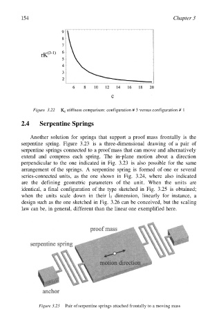
Another solution for springs that support a proof mass frontally is the
serpentine spring. Figure 3.23 is a three-dimensional drawing of a pair of
serpentine springs connected to a proof mass that can move and alternatively
extend and compress each spring. The in-plane motion about a direction
perpendicular to the one indicated in Fig. 3.23 is also possible for the same
arrangement of the springs. A serpentine spring is formed of one or several
series-connected units, as the one shown in Fig. 3.24, where also indicated
are the defining geometric parameters of the unit. When the units are
identical, a final configuration of the type sketched in Fig. 3.25 is obtained;
when the units scale down in their dimension, linearly for instance, a
design such as the one sketched in Fig. 3.26 can be conceived, but the scaling
law can be, in general, different than the linear one exemplified here.
Figure 3.23 Pair of serpentine springs attached frontally to a moving mass