
Page 172 - Mechanics of Microelectromechanical Systems
P. 172
3. Microsuspensions 159
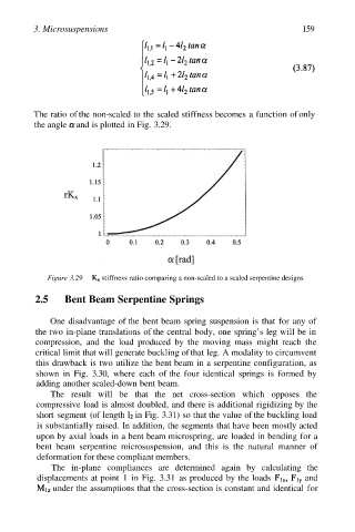
The ratio of the non-scaled to the scaled stiffness becomes a function of only
the angle and is plotted in Fig. 3.29.
Figure 3.29 stiffness ratio comparing a non-scaled to a scaled serpentine designs
2.5 Bent Beam Serpentine Springs
One disadvantage of the bent beam spring suspension is that for any of
the two in-plane translations of the central body, one spring’s leg will be in
compression, and the load produced by the moving mass might reach the
critical limit that will generate buckling of that leg. A modality to circumvent
this drawback is two utilize the bent beam in a serpentine configuration, as
shown in Fig. 3.30, where each of the four identical springs is formed by
adding another scaled-down bent beam.
The result will be that the net cross-section which opposes the
compressive load is almost doubled, and there is additional rigidizing by the
short segment (of length in Fig. 3.31) so that the value of the buckling load
is substantially raised. In addition, the segments that have been mostly acted
upon by axial loads in a bent beam microspring, are loaded in bending for a
bent beam serpentine microsuspension, and this is the natural manner of
deformation for these compliant members.
The in-plane compliances are determined again by calculating the
displacements at point 1 in Fig. 3.31 as produced by the loads and
under the assumptions that the cross-section is constant and identical for