
Page 177 - Mechanics of Microelectromechanical Systems
P. 177
164 Chapter 3
where is the direct linear bending stiffness of the compliant member
2-3, calculated at point 2 with respect to point 3 and in a local reference
frame placed at 2. Obviously, any of the hinge designs that have been
presented in Chapter 2 can be implemented in the sagittal microspring.
However, one complete sagittal microspring is composed of two identical
parts (as the one drawn in Fig. 3.34) that are connected in parallel, and thus
the total stiffness about the x-direction is:
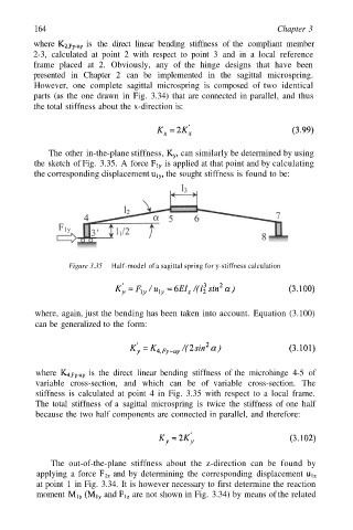
The other in-the-plane stiffness, can similarly be determined by using
the sketch of Fig. 3.35. A force is applied at that point and by calculating
the corresponding displacement the sought stiffness is found to be:
Figure 3.35 Half-model of a sagittal spring for y-stiffness calculation
where, again, just the bending has been taken into account. Equation (3.100)
can be generalized to the form:
where is the direct linear bending stiffness of the microhinge 4-5 of
variable cross-section, and which can be of variable cross-section. The
stiffness is calculated at point 4 in Fig. 3.35 with respect to a local frame.
The total stiffness of a sagittal microspring is twice the stiffness of one half
because the two half components are connected in parallel, and therefore:
The out-of-the-plane stiffness about the z-direction can be found by
applying a force and by determining the corresponding displacement
at point 1 in Fig. 3.34. It is however necessary to first determine the reaction
moment and are not shown in Fig. 3.34) by means of the related