
Page 179 - Mechanics of Microelectromechanical Systems
P. 179
166 Chapter 3
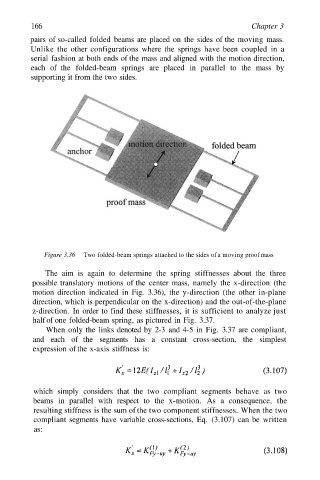
pairs of so-called folded beams are placed on the sides of the moving mass.
Unlike the other configurations where the springs have been coupled in a
serial fashion at both ends of the mass and aligned with the motion direction,
each of the folded-beam springs are placed in parallel to the mass by
supporting it from the two sides.
Figure 3.36 Two folded-beam springs attached to the sides of a moving proof mass
The aim is again to determine the spring stiffnesses about the three
possible translatory motions of the center mass, namely the x-direction (the
motion direction indicated in Fig. 3.36), the y-direction (the other in-plane
direction, which is perpendicular on the x-direction) and the out-of-the-plane
z-direction. In order to find these stiffnesses, it is sufficient to analyze just
half of one folded-beam spring, as pictured in Fig. 3.37.
When only the links denoted by 2-3 and 4-5 in Fig. 3.37 are compliant,
and each of the segments has a constant cross-section, the simplest
expression of the x-axis stiffness is:
which simply considers that the two compliant segments behave as two
beams in parallel with respect to the x-motion. As a consequence, the
resulting stiffness is the sum of the two component stiffnesses. When the two
compliant segments have variable cross-sections, Eq. (3.107) can be written
as: