
Page 184 - Mechanics of Microelectromechanical Systems
P. 184
3. Microsuspensions 171
the action of an external torque that is applied to the outer shaft, for
instance (case where the inner hub is supposed to be fixed), the relative
rotation angle is expressed by the equation:
The torsion stiffness is:
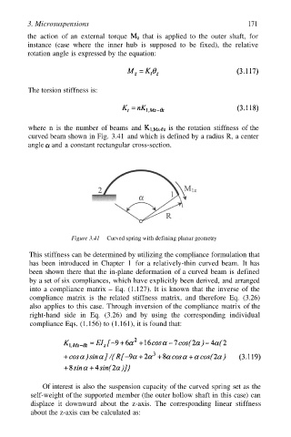
where n is the number of beams and is the rotation stiffness of the
curved beam shown in Fig. 3.41 and which is defined by a radius R, a center
angle and a constant rectangular cross-section.
Figure 3.41 Curved spring with defining planar geometry
This stiffness can be determined by utilizing the compliance formulation that
has been introduced in Chapter 1 for a relatively-thin curved beam. It has
been shown there that the in-plane deformation of a curved beam is defined
by a set of six compliances, which have explicitly been derived, and arranged
into a compliance matrix – Eq. (1.127). It is known that the inverse of the
compliance matrix is the related stiffness matrix, and therefore Eq. (3.26)
also applies to this case. Through inversion of the compliance matrix of the
right-hand side in Eq. (3.26) and by using the corresponding individual
compliance Eqs. (1.156) to (1.161), it is found that:
Of interest is also the suspension capacity of the curved spring set as the
self-weight of the supported member (the outer hollow shaft in this case) can
displace it downward about the z-axis. The corresponding linear stiffness
about the z-axis can be calculated as: