
Page 183 - Mechanics of Microelectromechanical Systems
P. 183
170 Chapter 3
By also using the other numerical values, one can study the sagittal-to-
folded-beam stiffness ratio which is plotted in Fig. 3.39 as a function of
the length of the folded beam. It can be seen that the sagittal design is
approximately 2.5 times stiffer than a corresponding folded-beam
configuration for small lengths of the middle compliant leg.
3. MICROSUSPENSIONS FOR ROTARY MOTION
Several microsuspensions are studied in this section, which are designed
for implementation in rotary-motion micromechanisms. Similar to the
microsuspension configurations that are used in linear-motion applications
and which were shown to be able to accommodate rotary motion as well, the
rotary microsprings can also be sensitive to linear motion.
3.1 Curved-Beam Springs
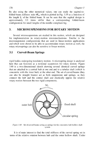
rigid bodies undergoing translatory motion. A microspring design is analyzed
here that can function as a torsional suspension for rotary motion. Figure
3.40 is a two-dimensional sketch showing several identical curved springs
that are attached to a central hub at one end and to a tubular shaft (which is
concentric with the inner hub) at the other end. The set of curved beams (they
can also be straight beams) act as both suspensions and springs, as they
connect the hub and the central shaft and elastically oppose the relative
rotary motion between the two rigid components.
Figure 3.40 Set of curved beams acting as springs for the concentric hub-hollow shaft
system
It is of main interest to find the total stiffness of the curved spring set in
terms of the relative rotation between hub and the outer hollow shaft. Under