
Page 175 - Mechanics of Microelectromechanical Systems
P. 175
162 Chapter 3
the bent beam to bent beam serpentine stiffness ratio can be evaluated in
terms of only the parameters and introduced in Eq. (3.95). Figure 3.32 is
the three-dimensional plot of this ratio, and it can be seen that the bent beam
design is stiffer than the corresponding bent beam serpentine variant.
2.6 Sagittal Springs
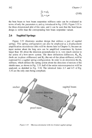
Figure 3.33 illustrates another design that utilizes a pair of sagittal
springs. This spring configuration can also be employed as a displacement
amplification microdevice (this will be shown later in Chapter 5), because an
input motion about the long axis can be amplified (sometimes by factors
larger than 10) about the direction perpendicular to it, very much similar to
the action of a bow-arrow system. The three definition stiffnesses,
(both are in-plane stiffnesses) and (the out-of-the-plane stiffness), will be
expressed for a sagittal spring configuration. In order to do determine the
stiffness, which defines the spring action about the direction of motion of the
shuttle mass, as shown in Fig. 3.33, half of the entire microsuspension will be
analyzed, as sketched in Fig. 3.34. The identical links 2-3 and 4-5 of Fig.
3.34 are the only ones being compliant.
Figure 3.33 Microaccelerometer with two frontal sagittal springs