
Page 199 - Mechanics of Microelectromechanical Systems
P. 199
186 Chapter 4
As Eq. (4.7) suggests‚ this relationship is fully determined by means of the
two parameters‚ the bloc force and the free displacement and therefore
these two amounts will be formulated for the types of actuators that behave
similarly.
2.2 Bent Beam
By changing the boundary conditions of the fixed-free bar analyzed
previously‚ bending and different levels of actuation can be achieved through
thermal heating‚ such as in the example of the bent beam (discussed also by
Que et al. [1] and Gianchandani and Najafi [2] for instance) that is sketched
in Fig. 4.3.
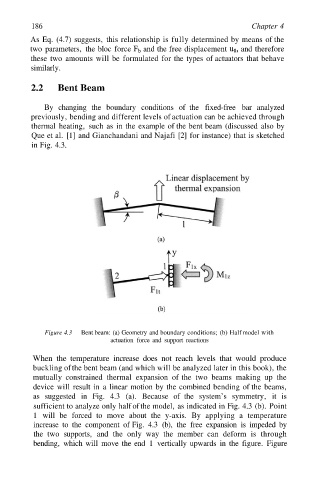
Figure 4.3 Bent beam: (a) Geometry and boundary conditions; (b) Half model with
actuation force and support reactions
When the temperature increase does not reach levels that would produce
buckling of the bent beam (and which will be analyzed later in this book)‚ the
mutually constrained thermal expansion of the two beams making up the
device will result in a linear motion by the combined bending of the beams‚
as suggested in Fig. 4.3 (a). Because of the system’s symmetry‚ it is
sufficient to analyze only half of the model‚ as indicated in Fig. 4.3 (b). Point
1 will be forced to move about the y-axis. By applying a temperature
increase to the component of Fig. 4.3 (b)‚ the free expansion is impeded by
the two supports‚ and the only way the member can deform is through
bending‚ which will move the end 1 vertically upwards in the figure. Figure