
Page 215 - Mechanics of Microelectromechanical Systems
P. 215
202 Chapter 4
If n such pairs are used, the total force will be n times larger than the force
given in Eq. (4.24). It is interesting to assess the relative force loss that
occurs when using the arrangement of Fig. 4.24 in comparison to the pure
one-pair transverse actuation, as shown in the following example.
Example 4.5
Compare the two-pair transverse actuator of Fig. 4.24 with the single-
pair design of Fig. 4.20 (a) in terms of the output force.
Solution:
By considering that the initial gap can be written as a fraction of the
actuator spacing as:
the following force ratio can be formed:
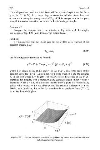
where F is given in Eq. (4.20) and F’ in Eq. (4.24). The force ratio of this
equation is plotted in Fig. 4.25 as a function of the fraction c and the distance
x, in the case where The relative force difference of Eq. (4.26)
increases non-linearly with c increasing and decreases quasi-linearly when x
increases. When c = 0.5, which means that the mobile plate is symmetrically
placed with respect to the two fixed plates, the relative difference is 1 (or
100%), as it should be, due to the fact that there is no resulting force (F’ = 0)
to act on the mobile plate.
Figure 4.25 Relative difference between force produced by simple transverse actuator pair
and interdigitated configuration