
Page 211 - Mechanics of Microelectromechanical Systems
P. 211
198 Chapter 4
In the majority of MEMS applications‚ the actuation force or the sensing
signal are insufficient when only one pair of moving-fixed parts are being
utilized. The practical solution to this problem is to couple several pairs of
such mating members in a comb-type configuration. Figure 4.19 sketches an
interdigitated pair with the main geometric parameters. The motion about
direction 1 in this figure is usually referred to as parallel-plate whereas the
other possible motion‚ about direction 2‚ is generally named comb-finger
motion. However‚ the interdigitated designs are used for both motions‚ and
therefore‚ in order to avoid confusion‚ the alternative denominations of
transverse and longitudinal will be used to indicate motions about the 1 and
2 directions‚ respectively.
These two types of motions are the main technological applications in
planar MEMS‚ and they will be presented in the following sub-sections. The
potentially-variable distances between the moving and fixed parts are the
gaps‚ denoted by and in Fig. 4.19 in order to indicate the axis they refer
to. Similarly‚ the thickness of a fixed/free member is indicated by either or
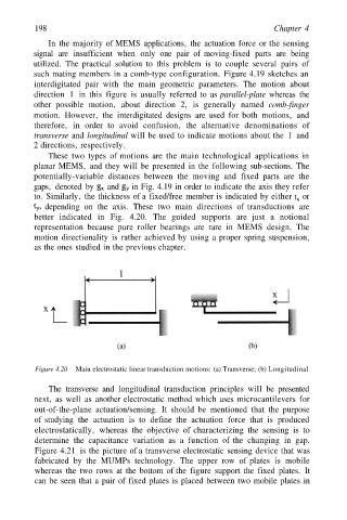
depending on the axis. These two main directions of transductions are
better indicated in Fig. 4.20. The guided supports are just a notional
representation because pure roller bearings are rare in MEMS design. The
motion directionality is rather achieved by using a proper spring suspension‚
as the ones studied in the previous chapter.
Figure 4.20 Main electrostatic linear transduction motions: (a) Transverse; (b) Longitudinal
The transverse and longitudinal transduction principles will be presented
next‚ as well as another electrostatic method which uses microcantilevers for
out-of-the-plane actuation/sensing. It should be mentioned that the purpose
of studying the actuation is to define the actuation force that is produced
electrostatically‚ whereas the objective of characterizing the sensing is to
determine the capacitance variation as a function of the changing in gap.
Figure 4.21 is the picture of a transverse electrostatic sensing device that was
fabricated by the MUMPs technology. The upper row of plates is mobile
whereas the two rows at the bottom of the figure support the fixed plates. It
can be seen that a pair of fixed plates is placed between two mobile plates in