
Page 312 - Mechanics of Microelectromechanical Systems
P. 312
5. Static response of MEMS 299
A similar approach is followed in order to determine the other important
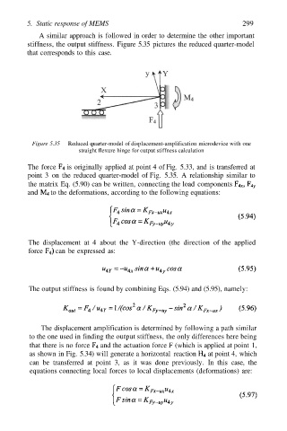
stiffness, the output stiffness. Figure 5.35 pictures the reduced quarter-model
that corresponds to this case.
Figure 5.35 Reduced quarter-model of displacement-amplification microdevice with one
straight flexure hinge for output stiffness calculation
The force is originally applied at point 4 of Fig. 5.33, and is transferred at
point 3 on the reduced quarter-model of Fig. 5.35. A relationship similar to
the matrix Eq. (5.90) can be written, connecting the load components
and to the deformations, according to the following equations:
The displacement at 4 about the Y-direction (the direction of the applied
force can be expressed as:
The output stiffness is found by combining Eqs. (5.94) and (5.95), namely:
The displacement amplification is determined by following a path similar
to the one used in finding the output stiffness, the only differences here being
that there is no force and the actuation force F (which is applied at point 1,
as shown in Fig. 5.34) will generate a horizontal reaction at point 4, which
can be transferred at point 3, as it was done previously. In this case, the
equations connecting local forces to local displacements (deformations) are: