
Page 310 - Mechanics of Microelectromechanical Systems
P. 310
5. Static response of MEMS 297
from Fig. 5.32 (b). By substituting now Eq. (5.87) into Eq. (5.86), the
following equation is obtained:
In the particular case where both the active force and the resistance force are
zero (the mechanism deforms through application of the input displacement
Eq. (5.88) simplifies to:
which shows that the displacement amplification a, the input stiffness and
the output stiffness are related. This condition is accurate for a device
with pure rotation joints, but is only an approximation for devices utilizing
microhinges, as shown in the following.
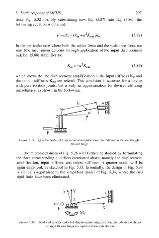
Figure 5.33 Quarter-model of displacement-amplification microdevice with one straight
flexure hinge
The micromechanism of Fig. 5.26 will further be studied by formulating
the three corresponding qualifiers mentioned above, namely the displacement
amplification, input stiffness and output stiffness. A quarter-model will be
again employed, as sketched in Fig. 5.33. Essentially, the design of Fig. 5.33
is statically-equivalent to the simplified model of Fig. 5.34, where the two
rigid links have been eliminated.
Figure 5.34 Reduced quarter-model of displacement-amplification microdevice with one
straight flexure hinge for input stiffness calculation