
Page 307 - Mechanics of Microelectromechanical Systems
P. 307
294 Chapter 5
the output port, about a direction perpendicular to the input one, due to the
inclination in the compliant legs, as shown in Fig. 5.26.
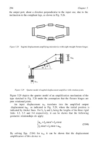
Figure 5.28 Sagittal displacement-amplifying microdevice with eight straight flexure hinges
Figure 5.29 Quarter model of sagittal displacement amplifier with rotation joints
Figure 5.29 depicts the quarter model of an amplification mechanism of the
type sketched in Fig. 5.26 under the assumption that the flexure hinges are
pure rotational joints.
An input displacement translates into the amplified output
displacement as indicated in Fig. 5.29, where the initial position is
indicated by thicker lines. For and being the lengths of the three rigid
links 1-2, 2-3 and 3-4 respectively, it can be shown that the following
geometric relationships do apply:
By solving Eqs. (5.84) for it can be shown that the displacement
amplification of this device is: