
Page 304 - Mechanics of Microelectromechanical Systems
P. 304
5. Static response of MEMS 291
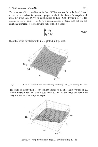
The notation of the compliances in Eqs. (5.78) corresponds to the local frame
of the flexure, where the y-axis is perpendicular to the flexure’s longitudinal
axis. By using Eqs. (5.78), in combination to Eqs. (5.66) through (5.71), the
displacements of point 1 in the two configurations of Figs. 5.21 (a) and (b)
can be determined. If the following substitution is used:
the ratio of the displacements is plotted in Fig. 5.23.
Figure 5.23 Ratio of horizontal displacements for point 1: Fig 5.21 (a) versus Fig. 5.21 (b)
The ratio is larger than 1 for smaller values of and larger values of
which means when the force F acts closer to the flexure hinge and when the
length of the flexure hinge is larger.
Figure 5.24 Amplification ratio: Fig 5.21 (a) versus in Fig. 5.21 (b)