
Page 301 - Mechanics of Microelectromechanical Systems
P. 301
288 Chapter 5
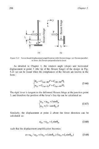
Figure 5.21 Lever-based displacement amplification with flexure hinge: (a) flexure parallel
to lever; (b) flexure perpendicular to lever
As detailed in Chapter 1, the rotation angle (slope) and horizontal
displacement at point 3 (the tip of the flexure hinge) of the design in Fig.
5.21 (a) can be found when the compliances of the flexure are known in the
form:
The rigid lever is tangent to the deformed flexure hinge at the junction point
3, and therefore the position of the lever’s free tip can be calculated as:
Similarly, the displacement at point 2 about the force direction can be
calculated as:
such that the displacement amplification becomes: