
Page 303 - Mechanics of Microelectromechanical Systems
P. 303
290 Chapter 5
By following a similar approach, the amplification for the case where the
axial deformations are neglected is:
The relative error between the amplifications given in Eq. (5.76) versus Eq.
(5.75) can be expressed as:
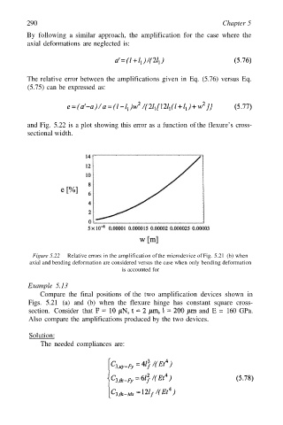
and Fig. 5.22 is a plot showing this error as a function of the flexure’s cross-
sectional width.
Figure 5.22 Relative errors in the amplification of the microdevice of Fig. 5.21 (b) when
axial and bending deformation are considered versus the case when only bending deformation
is accounted for
Example 5.13
Compare the final positions of the two amplification devices shown in
Figs. 5.21 (a) and (b) when the flexure hinge has constant square cross-
section. Consider that and E = 160 GPa.
Also compare the amplifications produced by the two devices.
Solution:
The needed compliances are: