
Page 309 - Mechanics of Microelectromechanical Systems
P. 309
296 Chapter 5
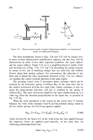
Figure 5.32 Physical quarter-model of sagittal displacement amplifier: (a) spring-based
model; (b) displacement diagram
The three mechanisms shown in Figs. 5.26 and 5.27 will be studied next
in terms of their displacement amplification capacity, but also they will be
characterized in terms of two other important qualifiers: the input stiffness
and the output stiffness. Figure 5.32 (a) is a simplified physical model of the
real microdevices of Figs. 5.26, 5.27 and 5.28 describing the spring features
by means of two sets of matching wedges that can relatively slip without
friction along their mating surfaces. For convenience, the subscript in has
been used to denote the input (horizontal) direction of Fig. 5.32 (a), whereas
out signifies the output (vertical) direction in the same figure.
The actuating (input) force F encounters elastic resistance which can be
modeled by the horizontal spring of stiffness At the same time, due to
the relative inclination of the two rigid links, elastic resistance is also set
about the perpendicular direction, and this is modeled by the spring of
stiffness The same inclination amplifies the input displacement to a
value about the direction perpendicular to the input one, as pictured in
Fig. 5.32 (b).
When the work introduced in the system by the action force F entirely
balances the work of the resistance force and the potential energy stored in
the two elastic springs, the following equation applies:
where division by the factor of 2 in the work terms has been applied because
the respective forces are applied quasi-statically. At the same time, the
following relationship holds true: