
Page 331 - Mechanics of Microelectromechanical Systems
P. 331
318 Chapter 5
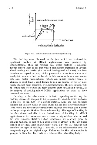
Figure 5.53 Bifurcation versus snap-through buckling
The buckling cases discussed so far (and which are retrieved in
significant numbers of MEMS applications) were produced by
bending/flexure. There are however cases where buckling is generated
through torsion (such as for thin-walled open-section members) or through
mixed bending and torsion (for coupled bending-torsional cases), but these
situations are beyond the scope of this presentation. Also, from a structural
standpoint, members that can buckle include columns (which can sustain
only axial loads), beam-columns (which can sustain bending loads, in
addition to axial loads), rigid frames (which are formed of two or more
rigidly-attached beam-columns), or plates/membranes. The presentation will
be limited here to columns and beam-columns (both straight and curved), as
the majority of buckling-related MEMS applications are based on these
structural members.
Buckling can be either elastic or inelastic, depending on the way the
buckling stresses do compare to the proportionality limit which is shown
in the plot of Fig. 5.54 for a ductile material. Long and thin (slender)
columns for instance buckle at stress levels that are less the proportionality
limit, where the stress-strain characteristic becomes non-linear (the material
no longer obeys the Hooke’s linear relationship). This type of buckling is
therefore elastic and this is the desired form of buckling in MEMS
applications, as the microcomponent recovers its original shape after the load
has been removed. Relatively short components are generally prone to
inelastic buckling, as part of their cross-section is already in the non-linear
portion of the stress-strain characteristic of Fig. 5.54 (the 2-3 portion), and
therefore this type of buckling is inelastic, so the micromember does not
completely regain its original shape. Unless the buckled micromember is
going to be discarded, this condition is to be avoided in buckling design.