
Page 330 - Mechanics of Microelectromechanical Systems
P. 330
5. Static response of MEMS 317
applied to the ball sitting at the top of the convex surface of Fig. 5.49 (c), the
ball will irreversibly move from its position UE, which is therefore an
unstable-equilibrium position. It should be mentioned that the three states of
Fig. 5.49 are defined based on small perturbations. When these perturbations
are large, there might be changes in the stability condition of a structure
leading, for instance, from a stable to an unstable state and vice versa.
Figures 5.50 and 5.51 illustrate two examples of structural buckling that
might be encountered in MEMS applications.
When the compression forces that are applied about the longitudinal
(long) axis of the thin member of Fig. 5.50 reach a certain critical level, the
column will lose its equilibrium position and will bend (buckle) outside its
plane as shown in the figure. Similarly, when the thin ring of Fig. 5.51 (a) is
compressed, it can buckle out of its plane, as illustrated in Fig. 5.51 (b). The
cases shown in Figs. 5.50 and 5.51 are representative for the bifurcation
buckling, where there is a sudden jump from one state/mode of deformation
(which is axial) to another mode (which is bending) at a critical level of the
compressive load. Another possibility is the limit-load or maximum-load
(also known as snap-through buckling – see Chen and Lui [6] for instance)
where the jump occurs between two modes that are similar in nature, such as
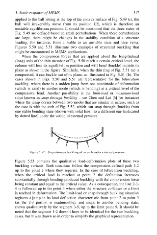
the case is with the arch of Fig. 5.52, which can snap-through (buckle) from
one stable bending state (shown with solid line), to a different one (indicated
by dotted line) under the action of external pressure.
Figure 5.52 Snap-through buckling of an arch under external pressure
Figure 5.53 contains the qualitative load-deformation plots of these two
buckling variants. Both situations follow the compression-defined path 1-2
up to the point 2 where they separate. In the case of bifurcation buckling,
when the critical load is reached at point 2 the deflection increases
substantially through bending-produced buckling with the compression force
being constant and equal to the critical value. As a consequence, the line 2-3-
4 is followed up to the point 4 where either the structure collapses or a limit
is reached in deformation. The limit-load or snap-through buckling situation
registers a jump in its load-deflection characteristic from point 2 to point 3
(as the 2-3 portion is inadmissible), and snaps to another bending state,
shown qualitatively by the segment 3-5, up to the limit point 5. It should be
noted that the segment 1-2 doesn’t have to be identical for the two buckling
cases, but it was drawn so in order to simplify the graphical representation.