
Page 334 - Mechanics of Microelectromechanical Systems
P. 334
5. Static response of MEMS 321
critical buckling load can be calculated for each case following the procedure
used in determining the critical load for a pinned-pined column, as detailed in
Chen and Lui [6] or Chajes [7]. The critical load can be expressed in the
generic manner:
where is called the effective length and is calculated by means of the
effective-length factor K as:
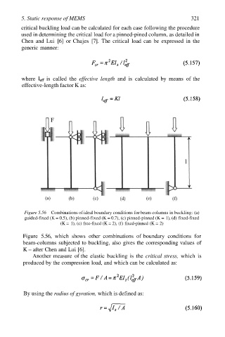
Figure 5.56 Combinations of ideal boundary conditions for beam-columns in buckling: (a)
guided-fixed (K = 0.5), (b) pinned-fixed (K = 0.7), (c) pinned-pinned (K = 1), (d) fixed-fixed
(K = 1), (e) free-fixed (K = 2), (f) fixed-pinned (K = 2)
Figure 5.56, which shows other combinations of boundary conditions for
beam-columns subjected to buckling, also gives the corresponding values of
K – after Chen and Lui [6].
Another measure of the elastic buckling is the critical stress, which is
produced by the compression load, and which can be calculated as:
By using the radius of gyration, which is defined as: