
Page 337 - Mechanics of Microelectromechanical Systems
P. 337
324 Chapter 5
One way of realizing condition (5.167) is to change the current boundary
conditions such that K increases. The highest theoretical value of K is 2, as
shown in Fig. 5.56, and this corresponds to either a free-fixed condition – Fig.
5.56 (e) or a fixed-pinned one – Fig. 5.56 (f). This provision would transform
Eq. (5.167) into:
because and as indicated in Fig. 5.56. As a consequence, the
microactuator will buckle elastically when the boundary is modified
according to the previous discussion and when the cross-section thickness is
reduced by at least 20%.
7.2.2 Curved Beam-Columns
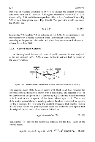
A pinned-pinned thin curved beam of small curvature is now analyzed,
as the one sketched in Fig. 5.58, in order to find its critical load by means of
the energy method.
Figure 5.58 Pinned-pinned curved beam of small curvature under axial loading
The original shape of the beam is drawn with thick solid line, whereas the
deformed (buckled) shape is shown with a dotted line. The original offset of
the curved beam at a position x is denoted by and the maximum offset
a is located at the midpoint of the beam whose span is 1. The extra-
deformation gained through axially-produced bending is denoted by
for the x-position. By following the standard procedure that enables finding
the deformed shape of a pinned-pinned beam and under the assumption that
the original curved shape of the beam is defined as:
Timoshenko [4] derived the following solution for the bent shape of the
curved beam: