
Page 341 - Mechanics of Microelectromechanical Systems
P. 341
328 Chapter 5
which is also the solution for a straight beam of length l.
7.3 Post Buckling and Large Deformations
The critical load is found by means of the small-displacement theory‚ and
this cannot predict the displacement/deformations of a beam-column at
buckling or for conditions where the axial load exceeds the critical value.
However‚ as mentioned previously‚ MEMS applications are being
specifically designed to produce large output displacement through buckling
and therefore knowledge of the true deformation of a buckled member is
important. By using the large-deformation theory it is possible to predict the
so-called post-buckling behavior of a microcomponent‚ as shown next.
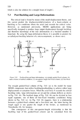
Figure 5.61 Postbuckling and large deformations: (a) straight guided-fixed column; (b)
same column in buckled condition; (c) one-quarter length free-fixed column; (d) free-fixed
column
The straight guided-fixed column of Fig. 5.61 (a) is the model for many
MEMS components that utilize buckling/postbuckling to achieve either large
displacements or actuation forces. When the axial force F exceeds the critical
buckling value‚ large deformations are set and the column deflects as shown
in Fig. 5.61 (b). The buckled shape of Fig. 5.61 (b) can be divided in four
equal segments‚ one of them (of free-fixed boundary conditions) being
shown in Fig. 5.61 (c). As Fig. 5.61 (b) suggests‚ there is a relationship
between a guided-fixed column and a free-fixed one‚ the latter having the
length equal to one quarter the length of the former‚ as mentioned by
Timoshenko [4]‚ for instance.
One consequence of this one-quarter-length relationship is that the
buckling load of the guided-fixed column can be calculated from the