
Page 339 - Mechanics of Microelectromechanical Systems
P. 339
326 Chapter 5
The advantage of the curved design, as well as of the next design
presented herein (the bent beam column), over the straight configuration is
that the curved beam-column produces buckling unidirectionally (outside the
curvature center), as it is improbable that buckling will occur the other
direction. This feature can be used in applications where buckling is sought
not to take place about certain directions, such as towards the substrate. At
the same time, the buckling direction of a straight beam-column is
completely unpredictable.
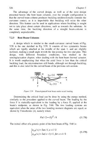
7.2.3 Bent Beam Columns
A design which is similar to the small-curvature curved beam of Fig.
5.58 is the one sketched in Fig 5.59. It consists of two symmetric beams
which are rigidly attached at the middle of the span 1, and are slightly
inclined, making a small angle with the line joining the two end pins. This
design, with different boundary conditions, was studied in the
sensing/actuation chapter, when dealing with the bent beam thermal actuator.
It is worth emphasizing that when the axial force is less than the critical
buckling load, the microstructure still bends, although not through buckling,
and this is also valid for the curved beam of the previous sub-section.
Figure 5.59 Pinned-pinned bent beam under axial loading
Determining the critical load can be done by using the energy method,
similarly to the procedure applied to the curved beam. The loading by the
force F is statically-equivalent to the loading by a force applied at the
beam’s midpoint, as shown in Fig. 5.60. The two loading systems are
equivalent when the areas of the two bending moment diagrams are equal, as
shown by Timoshenko [4], namely when:
The initial offset of a generic point of the bent beam of Fig. 5.60 is: