
Page 123 - Mechatronic Systems Modelling and Simulation with HDLs
P. 123
112 6 MECHANICS IN HARDWARE DESCRIPTION LANGUAGES
y b
y
a
Pos
Name:
Wheel suspension
Date:
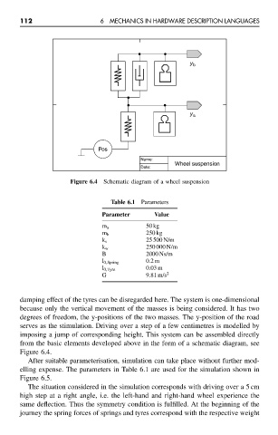
Figure 6.4 Schematic diagram of a wheel suspension
Table 6.1 Parameters
Parameter Value
m a 50 kg
m b 250 kg
k s 25 500 N/m
k w 250 000 N/m
B 2000 Ns/m
l 0,Spring 0.2 m
0.03 m
l 0,Tyre
G 9.81 m/s 2
damping effect of the tyres can be disregarded here. The system is one-dimensional
because only the vertical movement of the masses is being considered. It has two
degrees of freedom, the y-positions of the two masses. The y-position of the road
serves as the stimulation. Driving over a step of a few centimetres is modelled by
imposing a jump of corresponding height. This system can be assembled directly
from the basic elements developed above in the form of a schematic diagram, see
Figure 6.4.
After suitable parameterisation, simulation can take place without further mod-
elling expense. The parameters in Table 6.1 are used for the simulation shown in
Figure 6.5.
The situation considered in the simulation corresponds with driving over a 5 cm
high step at a right angle, i.e. the left-hand and right-hand wheel experience the
same deflection. Thus the symmetry condition is fulfilled. At the beginning of the
journey the spring forces of springs and tyres correspond with the respective weight