
Page 128 - Mechatronic Systems Modelling and Simulation with HDLs
P. 128
6.3 CONTINUUM MECHANICS 117
Finite elements
In principle, finite elements can be used in many fields of engineering science. Our
discussion is based upon the field of structural mechanics. Thus the following quan-
tities have to be linked together: displacements, forces, strain, and applied loads,
which act as a trigger here. Depending upon the application, different finite ele-
ments are used, which vary in structure, number of nodes and degrees of freedom.
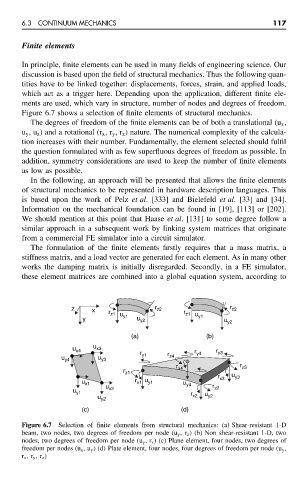
Figure 6.7 shows a selection of finite elements of structural mechanics.
The degrees of freedom of the finite elements can be of both a translational (u x ,
u y ,u z ) and a rotational (r x ,r y ,r z ) nature. The numerical complexity of the calcula-
tion increases with their number. Fundamentally, the element selected should fulfil
the question formulated with as few superfluous degrees of freedom as possible. In
addition, symmetry considerations are used to keep the number of finite elements
as low as possible.
In the following, an approach will be presented that allows the finite elements
of structural mechanics to be represented in hardware description languages. This
is based upon the work of Pelz et al. [333] and Bielefeld et al. [33] and [34].
Information on the mechanical foundation can be found in [19], [113] or [202].
We should mention at this point that Haase et al. [131] to some degree follow a
similar approach in a subsequent work by linking system matrices that originate
from a commercial FE simulator into a circuit simulator.
The formulation of the finite elements firstly requires that a mass matrix, a
stiffness matrix, and a load vector are generated for each element. As in many other
works the damping matrix is initially disregarded. Secondly, in a FE simulator,
these element matrices are combined into a global equation system, according to
z x r z1 u r z2 r z1 u r z2
y y1 u y2 y1 u y2
(a) (b)
u x4 u x3 r r r y3
u y4 u y3 y1 r z4 y4
r r z3
r z1 x4
r x3 u y3
u x1 r x1 u y1 u y4
u y1 u x2 r r z2
u y2 x2 u y2
(c) (d)
Figure 6.7 Selection of finite elements from structural mechanics: (a) Shear-resistant 1-D
beam, two nodes, two degrees of freedom per node (u y ,r z ) (b) Non shear-resistant 1-D, two
nodes, two degrees of freedom per node (u y ,r z ) (c) Plane element, four nodes, two degrees of
freedom per nodes (u x ,u y ) (d) Plate element, four nodes, four degrees of freedom per node (u y ,
r x ,r y ,r z )