
Page 131 - Mechatronic Systems Modelling and Simulation with HDLs
P. 131
120 6 MECHANICS IN HARDWARE DESCRIPTION LANGUAGES
z x r r z1
z0 u y0
y u y1
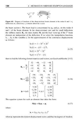
Figure 6.8 Degrees of freedom of the shear-resistant beam element at the nodes k and l: u y
(deflection in y-direction), r z (rotation about the z-axis)
the beam section i. The beam load is concentrated by p i0 and p i1 on the nodes 0
and 1 of the beam element. In the shear-resistant case and for small deflections
th
the stiffness matrix K i , the mass matrix M i and the load vector p i of the i beam
element are independent of the deflection. If we select the interpolation functions
h 1 ... h 4 in the variables ξ for the approximation of the continuous displacements
as follows:
2
h 1 (ξ) = 1 − 3ξ + 2ξ 3
2
h 2 (ξ) =−ξ(1 − ξ) l i
(6.35)
2
h 3 (ξ) = 3ξ − 2ξ 3
2
h 4 (ξ) = ξ (1 − ξ)l i
then we find the following element matrices and vectors, see Gasch and Knothe [113]:
12 −6l i −12 −6l i
B i −6l 4l 2 6l i 2
i
K i = i 2l
3
l −12 6l i 12
i 6l i
−6l 2l 2 6l i 4l 2
i i
156 −22l i 54 13l i
2 2
µ i l i −22l i 4l i −13l i −3l
i
M i = (6.36)
54 −13l i 156
420 22l i
13l i −3l 2 22l i 4l 2
i i
7/20 3/20
−l i /20 −l i /30
p i = p i0 l i + p i1 l i
3/20 7/20
l i /3 l i /20
The equation system for such an element thus takes the form:
(6.37)
M i ¨u i + K i u i = p i
where
u i = [u y0 , r z0 , u y1 , r z1 ] T
where u i represents the element displacement vector, and thus the degrees of freedom.