
Page 143 - Mechatronics for Safety, Security and Dependability in a New Era
P. 143
Ch26-I044963.fm Page 127 Tuesday, August 1, 2006 3:00 PM
3:00 PM
Tuesday, August 1, 2006
Page 127
Ch26-I044963.fm
127
127
Rigid translational
Contact finger 1 Rigid translational Contact
Contact finger 1
driving joint
driving joint Contact
Rigid rotational finger 1 92.3 mm
Rigid rotational
driving joint Rigid rotational free Y
driving joint
Rigid rotational free
60.0°
joint by a contact plate
Contact
Contact joint by a contact plate Veo.r
with a thin rubber
finger 4
finger 4 with a thin rubber
Work (12, 35) 92.1 mm
12, 35)
Work
Contact
Contact Contact (35, 12)
(35, 12)
finger 4
finger 2 finger 4 62.2°
O O X X
Elastic rotational free 91.8 mm (-35, 10) Contact
Elastic rotational free
Contact
91.8 mm
-35,
10)
joint by a contact plate
joint by a contact plate (-10, 35 finger 2
finger 2
(-10, 35)
63.8°
with a thick rubber 63.8°
with a thick rubber
Rigid rotational
Rigid rotational
/ driving joint 53.3°
driving joint
Elastic translational driving joint
Elastic translational driving joint
92.0 mm Contact
Contact
finger 3
finger 3
Contact finger 3
Contact finger 3
(a) Characteristic of each joint (b) Coordinates of each contact point in experiments
(a) Characteristic of each joint (b) Coordinates of each contact point in experiments
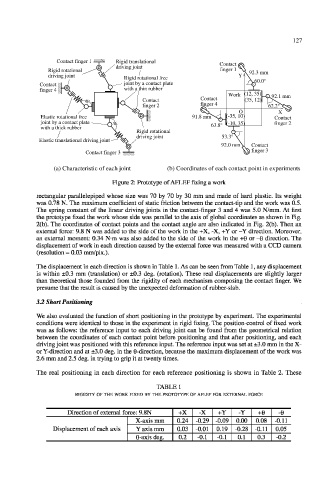
Figure 2: Prototype of AFLEF fixing a work
rectangular parallelepiped whose size was 70 by 70 by 30 mm and made of hard plastic. Its weight
was 0.78 N. The maximum coefficient of static friction between the contact-tip and the work was 0.5.
The spring constant of the linear driving joints in the contact-finger 3 and 4 was 5.0 N/mm. At first
the prototype fixed the work whose side was parallel to the axis of global coordinates as shown in Fig.
2(b). The coordinates of contact points and the contact angle are also indicated in Fig. 2(b). Then an
external force: 9.8 N was added to the side of the work in the +X, -X, +Y or -Y direction. Moreover,
an external moment: 0.34 N-m was also added to the side of the work in the +6 or -6 direction. The
displacement of work in each direction caused by the external force was measured with a CCD camera
(resolution = 0.03 mm/pix.).
The displacement in each direction is shown in Table 1. As can be seen from Table 1, any displacement
is within ±0.3 mm (translation) or ±0.3 deg. (rotation). These real displacements are slightly larger
than theoretical those founded from the rigidity of each mechanism composing the contact finger. We
presume that the result is caused by the unexpected deformation of rubber-slab.
3.2 Short Positioning
We also evaluated the function of short positioning in the prototype by experiment. The experimental
conditions were identical to those in the experiment in rigid fixing. The position-control of fixed work
was as follows: the reference input to each driving joint can be found from the geometrical relation
between the coordinates of each contact point before positioning and that after positioning, and each
driving joint was positioned with this reference input. The reference input was set at ±3.0 mm in the X-
or Y-direction and at ±3.0 deg. in the 0-direction, because the maximum displacement of the work was
2.6 mm and 2.5 deg. in trying to grip it at twenty times.
The real positioning in each direction for each reference positioning is shown in Table 2. These
TABLE 1
RIGIDITY OF THE WORK FIXED BY THE PROTOTYPE OF AFLEF FOR EXTERNAL FORCE
Direction of external force: 9.8N +X -X +Y -Y +0 -e
X-axis mm 0.24 -0.29 -0.09 0.00 0.08 -0.11
Displacement of each axis Y axis mm 0.03 -0.01 0.19 -0.28 -0.11 0.05
0-axis deg. 0.2 -0.1 -0.1 0.1 0.3 -0.2