
Page 261 - Mechatronics for Safety, Security and Dependability in a New Era
P. 261
Ch49-I044963.fm Page 245 Tuesday, August 1, 2006 4:04 PM
4:04 PM
Page 245
Tuesday, August
1, 2006
Ch49-I044963.fm
245
245
(D .
m*
C3)«
® •
<s>*
© •
0 10 20 30 40 50 60 70
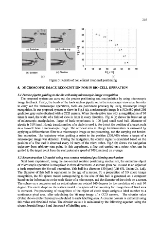
(c) Suction (d) Fixation
(a) (b)
Figure 5: Results of non contact rotational positioning
5. MICROSCOPIC IMAGE RECOGNITION FOR IN BIO-CELL OPERATION
5.1 Precise pipette guiding to the bio cell using microscopic image recognition
The proposed system can carry out the precise positioning and manipulation by using microscopic
image feedback. Firstly, the heads of the tools such as pipette set in the microscope view area. In order
to carry out the microscopic operations, tools are positioned precisely by using microscope image
recognition. In our proposed system as show in Fig.l (a), a microscopic image is a 512x480-pixel 256
gradation gray scale obtained with a CCD camera. When the objective lens with a magnification of 10
times is used, the width of a field of view is lmm in every direction. Fig. 6 (a) shows the basic set up
of microscopic manipulation. Target of basic experiment is 100 [iim] small steel ball. Diameter of
pipette is 100 [um]. Hough transformation of a circle is used to for detect the position of a target such
as a bio-cell from a microscopic image. The retrieval area in Hough transformation is narrowed by
applying a differentiation filter to a microscopic image as pre-processing, and the carrying out border-
line extraction. The trajectory when guiding a robot to the position (200,400) where a target of a
microscopic image was detected. During the navigation, the control signal is calculated based on the
position of a fine tool is observed every 10 steps of the micro robot. Fig.6 (b) shows the navigation
trajectory from arbitrary start point. In this experiment, a fine tool carried on a micro robot can be
guided to the target point from the start point at a speed of 100 [urn /sec] on average.
5.2 Reconstruction 3D model using non contact rotational positioning mechanism
Next basic experiment, using the non-contact rotation positioning mechanism, the miniature object
of microscopic operation is recognized in three dimensions. A minute glass ball is used as an object of
a basic experiment for bio cell operations. This ball is a diameter 130 [iim] (UB-67L Union Co. Ltd).
The diameter of this ball is equivalent to the egg of a mouse. To a preparation of 3D micro image
recognition, the 3D sphere model corresponding to the size of this ball is generated on a computer
based on the information on the scale factor of a microscope, and the diameter of the circle on a screen.
The sphere on a computer and an actual sphere are rotated 360 degrees by the resolution of a unit 10
degree. The circle shape on the surface model of a sphere of the boundary for recognition of front area
is extracted. Pre-processing of recognition of the object of circle shape assigns a label number to a
continuous pixel area, after calculating the bit map image of a CCD camera. The circular value
(Value shows circle-likeness) is calculated to each labelling area. A circular domain is extracted using
this value and threshold value. The circular value e is calculated by the following equation using the
circumferential length / and the area S of labelling area .