
Page 408 - Mechatronics for Safety, Security and Dependability in a New Era
P. 408
Ch79-I044963.fm Page 392 Saturday, July 29, 2006 7:14 AM
Ch79-I044963.fm
392
392 Page 392 Saturday, July 29, 2006 7:14 AM
Return Loss (high band)
Frequency [GHz]
Pin = OdBm Pin = -5dBm
Output DC voltage — Output DC voltage
Efficiency u Efficiency
l.b | , —i 60
- - - —
10 " " " - -::>-.; 30
- n -, - , r^^ n 1 n m 20
5.4 5.5 5.6 5.7 5.8 5.9 6.0 6.1 6.2 2,30 2,35 2.40 2.45 2.50 2.55 2,60
Frequency [GHz] Frequency [GHz]
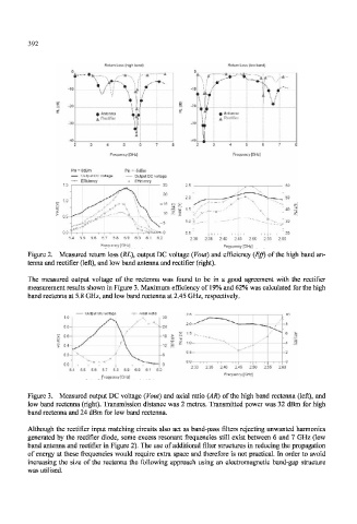
Figure 2. Measured return loss (RL), output DC voltage (Vout) and efficiency (Eff) of the high band an-
tenna and rectifier (left), and low band antenna and rectifier (right).
The measured output voltage of the rectenna was found to be in a good agreement with the rectifier
measurement results shown in Figure 3. Maximum efficiency of 19% and 62% was calculated for the high
band rectenna at 5.8 GHz, and low band rectenna at 2.45 GHz, respectively.
Output DC voltage •::• Axial Ratio
1.0 30
08 24
/ 1 5
> 06 - s i ' -
I 0.4^ H $ 1.0-
0.2-
—.
00
2.30 2 35 2.40 2.45 2.50 2 55 2 6
5.4 5.5 5.6 5.7 5.8 5.9 6.0 6.1 6.2
Frequency [GHz]
Frequency [GHz]
Figure 3. Measured output DC voltage (Vout) and axial ratio (AR) of the high band rectenna (left), and
low band rectenna (right). Transmission distance was 2 metres. Transmitted power was 32 dBm for high
band rectenna and 24 dBm for low band rectenna.
Although the rectifier input matching circuits also act as band-pass filters rejecting unwanted harmonics
generated by the rectifier diode, some excess resonant frequencies still exist between 6 and 7 GHz (low
band antenna and rectifier in Figure 2). The use of additional filter structures in reducing the propagation
of energy at these frequencies would require extra space and therefore is not practical. In order to avoid
increasing the size of the rectenna the following approach using an electromagnetic band-gap structure
was utilised.