
Page 415 - Mechatronics for Safety, Security and Dependability in a New Era
P. 415
Ch80-I044963.fm Page 399 Tuesday, August 1, 2006 4:54 PM
1, 2006
Page 399
Tuesday, August
Ch80-I044963.fm
4:54 PM
399
399
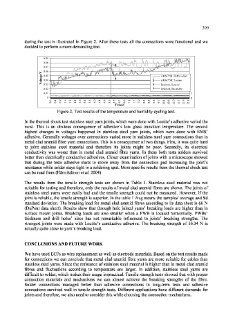
during the test is illustrated in Figure 2. After these tests all the connections were functional and we
decided to perform a more demanding test.
0.09
0.08
3
0.07
V 0.06
/
e 0.05 ARACON, SnPb-solder
g ARACON, SnPb-solder
a 4 1
t
ARACON, Loctite
l 0.04 2 2 ARACON, Loctite
o
V 0.03 3 3 Bekinox, Loctite
Bekinox, Loctite
0.02 4 Bekinox, Sn-solder
Bekinox, Sn-solder
0.01 2
0
0 4 9 3 8 2 6 1 5 0 4 9 3 7 2 6 1 5 9 4 8 3 7 1 6 0 5 9 3 1
. . . . . . . . . . . . . . . . . . . . . . . . . . . . .
0 0 o 0 -* 1 -* 1 2 2 3 3 4 4 4 5 5 6 6 7 7 7 8 8 9 9 0 0 1 1 1 2
Time/d 1 1 1 1 1 1
Time/d
Figure 2. Test results of the temperature and humidity cycling test.
In the thermal shock test stainless steel yarn joints, which were done with Loctite's adhesive varied the
most. This is an obvious consequence of adhesive's low glass transition temperature. The second
highest changes in voltages happened in stainless steel yarn joints, which were done with EMS'
adhesive. Generally voltages over connections varied more in stainless steel yarn connections than in
metal clad aramid fibre yarn connections. This is a consequence of two things. First, it was quite hard
to joint stainless steel material and therefore its joints might be poor. Secondly, its electrical
conductivity was worse than in metal clad aramid fibre yarns. In these both tests solders survived
better than electrically conductive adhesives. Closer examination of joints with a microscope showed
that during the tests adhesive starts to move away from the connection pad increasing the joint's
resistance while solder stays tight in a soldering spot. More specific results from the thermal shock test
can be read from (Hannikainen et al. 2004)
The results from the tensile strength tests are shown in Table 1. Stainless steel material was not
suitable for testing and therefore, only the results of metal clad aramid fibres are shown. The joints of
stainless steel yarns were easily bad and the tensile strength could not be measured. However, if the
joint is reliable, the tensile strength is superior. In the table 1 Avg means the samples' average and Sd
standard deviation. The breaking load for metal clad aramid fibres according to its data sheet is 66 N
(DuPont data sheet). Results show that through hole joined yarns' breaking loads are higher than in
surface mount joints. Breaking loads are also smaller when a PWB is located horizontally. PWBs'
thickness and drill holes' sizes has not remarkable influenced to joints' breaking strengths. The
strongest joints were made with Loctite's conductive adhesive. The breaking strength of 56.34 N is
actually quite close to yarn's breaking load.
CONCLUSIONS AND FUTURE WORK
We have used ECFs as wire replacement as well as electrode materials. Based on the test results made
for connections we can conclude that metal clad aramid fibre yarns are more suitable for cables than
stainless steel yarns. Since the resistance of stainless steel material is higher than in metal clad aramid
fibres and fluctuations according to temperature are larger. Tn addition, stainless steel yarns are
difficult to solder, which makes their usage impractical. Tensile strength tests showed that with proper
connection materials and mechanisms we can almost achieve the breaking strengths of the fibre.
Solder connections managed better than adhesive connections in long-term tests and adhesive
connections survived well in tensile strength tests. Different applications have different demands for
joints and therefore, we also need to consider this while choosing the connection mechanisms.