
Page 441 - Mechatronics for Safety, Security and Dependability in a New Era
P. 441
Ch85-I044963.fm Page 425 Monday, August 7, 2006 11:32 AM
Page 425
Monday, August 7,2006
11:32 AM
Ch85-I044963.fm
425
425
dynamics, interpolations, position feedback controller, input/output single processors, and teaching
function.
Accurate Position Control Algorithm
Fig.4 shows the control scheme. The output commands of the upper level include position and speed
references for the servo cylinder controllers.
Figure 4: Position control scheme
The servo control loops consist of position loops and speed loops that provide accurate and fast
trajectory tracking. The load pressure feedback loops are used for damping the self-excited oscillations
normally occurring in natural frequency. The speed loop can eliminate the speed error, while the
pressure feedback damps the vibration of the hydraulic actuator. The hydraulic cylinders normally lack
damping that make their control difficult by using conventional PID-controllers. The damping can
effectively be increased by means of load pressure feedback. The major drawback in using pressure
feedback is its negative effect on the static stiffness of the actuator. To overcome this high pass filters
are used in the load pressure feedback loops. The high pass filter removes the negative effect of
pressure feedback at low frequencies.
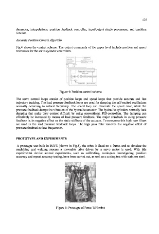
PROTOTYPE AND EXPERIMENTS
A prototype was built in 1MVE (shown in Fig.5), the robot is fixed on a frame, and to simulate the
machining and welding process a moveable table driven by a servo motor is used. With this
experimental device several experiments, such as calibrating, workspace investigating, position
accuracy and repeat accuracy testing, have been carried out, as well as a cutting test with stainless steel.
Figure 5: Prototype of Penta-WH robot