
Page 440 - Mechatronics for Safety, Security and Dependability in a New Era
P. 440
Ch85-I044963.fm Page 424 Monday, August 7, 2006 11:32 AM
Ch85-I044963.fm
424
424 Page 424 Monday, August 7,2006 11:32 AM
According to the principle of virtual work, we have
(6)
Substitute Eqn.5 into Eqn.6 we have
T
P=(J"') F (7)
The force in the cylinder can be obtained from Eqn.7 once a certain payload is given at the end tip.
Considering the friction force is small, this force can also be regarded as the main force in the bearings.
The above models help to investigate the workspace, force capacity, singularity and stiffness to achieve
an optimised structure [6]. A multi-body simulation model of robot has also been built to check the
deflections, workspace and collisions as well. With optimisation design the robot can reach a larger
:
singularity free workspace than the required200 x 200 x 300mm ', achieve high stiffness up to 400N/(im
for the universal joints unit and 315N/|am for the carriage, and has high force capacity able to carry the
heavy welding gun and take high machining forces.
CONTROL SYSTEM
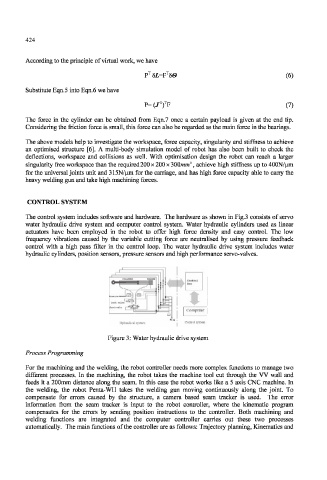
The control system includes software and hardware. The hardware as shown in Fig.3 consists of servo
water hydraulic drive system and computer control system. Water hydraulic cylinders used as linear
actuators have been employed in the robot to offer high force density and easy control. The low
frequency vibrations caused by the variable cutting force are neutralised by using pressure feedback
control with a high pass filter in the control loop. The water hydraulic drive system includes water
hydraulic cylinders, position sensors, pressure sensors and high performance servo-valves.
Hydraulics! sysb
Figure 3: Water hydraulic drive system
Process Programming
For the machining and the welding, the robot controller needs more complex functions to manage two
different processes. In the machining, the robot takes the machine tool cut through the VV wall and
feeds it a 200mm distance along the seam. In this case the robot works like a 5 axis CNC machine. In
the welding, the robot Penta-WH takes the welding gun moving continuously along the joint. To
compensate for errors caused by the structure, a camera based seam tracker is used. The error
information from the seam tracker is input to the robot controller, where the kinematic program
compensates for the errors by sending position instructions to the controller. Both machining and
welding functions are integrated and the computer controller carries out these two processes
automatically. The main functions of the controller are as follows: Trajectory planning, Kinematics and